3D Test & Alignment Chart
Story Highlights
Cinematographer Sean Fairburn, “after 6 years talking about it,” has “spent 3 Days with DSCLabs.com designing a Complete 3D Alignment chart for use with Side by Side and Beamsplitter Rigs. This Chart has built in many features I always need during Prep and testing and in the Field shot for shot. It is also intended to be recorded to allow Post to have a Point of reference as well to Dial in the 3D rigs more precisely more quickly.”
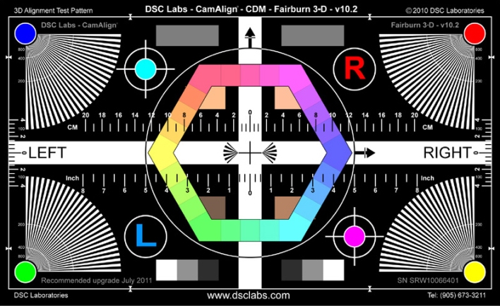
Here’s a look at the chart:
And here’s a link to the chart’s page on the DSC Labs site: http://dsclabs.com/Fairburn%203D.htm
Fairburn offers this preliminary list of features and procedures, saying he will post more later on the DSC site (where the chart is available for purchase):
Feature tools include:
• Horizontal and Vertical Alignment (White Cross through middle “Superwhite” and small crosses)
• Focus Fans in corners (Maximum contrast for ease of viewing even in Low light)
• Zoom Ring 10″ in diameter (to see zoom disparity between cameras focal length) 5 pixels
• Keystone Correction (colored Balls and White rings in corners)
• Horizontal Scale in cm and Inches (to see exact IO offset at Parallel)
• Mini Gray Scale (Swatch at Bottom #1 White, #6 Middle Gray, #11 Black + “Superblack”.08)
• 18% Gray Scale Chips (at top of chart on RT and LT)
• Chroma Du Mond Color Reference in Hexagon Shape (which matches Vector Scope orientation)
• RIGHT and LEFT words on white lines used as orientation detectors
• Arrows Up and Right Also used as Orientation detectors (base of Triangle is 40 Pixels)
• Red R and Blue L to show Color and eye reference (Red Right eye-Blue Left eye)
• RED R show image Flip or Flop orientation
• RGB&YCM have been added at highest printable value.
• Focus Fans at the Center are for zoomed in focus Aide.
• Scale on far R & L to measure Horiz and rotational offset.
• Dead Center Cross.
3D Test Chart Procedures:
DURING PREP:
Set up the Chart on a C Stand with the Mounting Stand.
Use Level and tape or laser to measure height of Center Chart match height of Center Lens
Chart should be flat to the image plane so that distance to sides match and top bottom match.
Light Chart so no reflections appear on chart.
Lenses must Track through Zoom. Set up each Camera on Head seperately before mounting 3D rig to Head and Cameras to Rig.
Mount lens to Camera widen out center crosshairs on chart now zoom in and mark location of crosshairs at telephoto. If it is not centered on the chart to the sensor adjustment in tracking must be done by Lens Tech. Once done this lens and Camera are “Married” and should not be separated. Rods and motors lens brackets should all be Set and Snug then Kept together.
Color Adjustment can also be done and saved as LUT’s or Scene Files (You will do this again once mounted to camera rig with beamsplitter)
Right Eye Camera should be marked with RED tape (RED RIGHT) on 2nd Rigg (YELLOW RIGHT)
Left Eye Camera should be marked with BLUE tape (BLUE LEFT) on 2nd Rigg (GREEN LEFT)
Mount the 3-D Rigg to Head.
Begin 3D Camera Setup by Mechanically zeroing out everything from the camera Tripod, head, rig mount, and camera mounting plates. Level head, level & plumb both plates.
Mount Cameras and lenses (Already together) to Rigg so that they are same distance to reflective surface Mirror.
If Side by Side insure they match forward or backward.
Insure Focus, Iris, Zoom, match and are set the same.
Even the best rigs may have some degree of offset between them therefore having an Alignment chart gives a Common critical reference point for the 2 Cameras to be brought into Alignment and to match. Rolling on the chart will also give a tool for Post to continue the work or adjust as needed later.
If using a Beam Splitter 50/50 Mirror. Best Viewed on a 50/50 Overlay monitor (One Half dissolved between the 2 images)
Drive the IO and C to ZERO called “ZERO Inter-ocular”
Goal here is to make the cameras see exactly the same thing the same vector on all objects in the shot.
They should match exactly in:
1) Horizontal
2) Vertical
3) Zoom Size
4) Focus Distance
5) Rotation
6) Iris
7) Black/White/Mid/Color
8) Genlock
9) Shutter Sync
10) Equal distant Cables from cameras to Recorders, Switchers and Monitors.
Now the Chart becomes a Reference Tool to see exactly how each camera is aligned and if adjustments need to be made.
Final Color Adjustments through the Beamsplitter must also be made to match the color of both cameras to Match.
IN THE FIELD:
Measure the distance to the chart and note that distance and focal length.
Use the 3-D Chart for morning setup and at the beginning of every scene to give an Alignment and color reference to Post to continue the adjustments if needed.
At the head of every Tape or scene.
Cover the Left Side markings of the Chart, Roll the Right Eye only.
Cover the Right Side markings of the Chart, Roll the Left Eye only.
Record the chart with both Cameras.
It would be nice to Set Convergence to INFINITY first to show your Inter-Ocular distance.
Then show the Chart Converged. Then set the convergence where you want for the scene.
Chart Distance Consistency will be helpful in post when possible.
Good Habit at the head of a Scene First Shot
Roll on Chart till Speed, then Mark with Sync Slate, begin the Shot.
Another Good Habit is to Tail Stick every Shot as well to look for drift in cameras.
IN POST:
When syncing 2 eyes use the 3-D chart as a reference for H & V, Zoom, Rotation, proper convergence Setting.