Comments on the Tessive Time Filter
Story Highlights
In a previous post, I described the Tessive Time Filter, subject of a presentation and demonstration at February’s HPA Tech Retreat. John Watkinson submitted a comment on it, and Tony Davis, Tessive’s founder, responded. First, here is John’s comment:
The Tessive LCD shutter
Numerous claims have been made for this device which I consider here. Tessive claim that it is an anti-aliasing filter. However, every anti-aliasing filter I have ever seen causes of necessity substantial reduction in level before or at half the sampling rate. The Tessive device does not, which is no surprise because that is not possible in a device that goes in front of a camera lens.
Filters can only reduce or enhance parts of the input spectrum that already exist. They do not produce new frequencies. The Tessive device creates new frequencies (sidebands) that did not exist in the original image and so it is not a filter. In fact it is an amplitude modulator and from Tessive’s own web site it can be seen mathematically to act like an amplitude modulator. Amplitude modulators produce sidebands and the Tessive device is no exception.
The window function of the Tessive modulator appears to be roughly Gaussian, and so the frequency response, which is the Fourier transform of the window function, will also be Gaussian, which can be seen in their own response chart. This chart shows a significant response at half the sampling rate, 12Hz, falling steadily to around 40Hz. Consequently the device will be wide open to aliasing between 12 and 40 Hz.
Tessive’s web site describes the “wagon wheel” effect seen in movies as an example of aliasing, but they fail to state that their device cannot deal with it. A typical stagecoach has wheels about 5 feet in diameter with around 14 spokes. At 10mph, a not unusual speed, the spoke passing frequency is about 12.5Hz. This will cause aliasing with any 24Hz camera that the Tessive unit is powerless to prevent. The same will be true right up to the maximum speed of a stagecoach.
Tessive also demonstrate a spoked spinning disc that appears not to alias with their system. However, the demonstration is contrived. The disc rotates at 5Hz and produces spoke passing frequencies of 40, 70 and 75 Hz, all above the frequency band where their device does not work. If the video is stopped near the beginning, it will be seen that the once-round bar has sharp edges whereas the remaining bars all have pre-softened edges to make the bars smear better when turning. This could not have been accidental. If the demonstration was repeated at half the speed (2.5Hz) powerful aliasing would be visible which the Tessive device cannot prevent.
If Tessive’s clip of a helicopter is considered, the rotor will be seen to have four blades both with and without the Tessive device in action. However, that model of helicopter only has two blades and it appears to have four because of aliasing that the Tessive has not prevented.
Tessive’s device produces interesting effects and may be useful in some circumstances, but it is not an anti-aliasing filter and it is a pity that they have exaggerated its capabilities, described it with pseudoscience and given contrived demonstrations.
John Watkinson
————————————————————————————————-
Here is Tony’s response:
John,
Regarding your post:
Let me introduce myself: I’m Tony Davis, the founder of Tessive and the presenter in our videos, and the designer of the Time Filter. The name is a play on words: it’s a shutter, but it fits into the filter tray of the camera, and its effect as a shutter synchronized with the integrating sensor is also temporal lowpass filtering. It’s designed to specifically address an issue related to current shutters and imaging technology.
I’d like to convince you that our product is not “pseudo-science”. It truly isn’t, and the mathematics are quite solid. So let me start with the patterned wheel demonstration, which is posted on our website at http://www.tessive.com/home/demo-footage. You are correct, the spokes in our demonstration are soft. That’s because that disk is designed with sine waves, not square waves, for the fundamental frequencies. It’s not meant as a trick, it’s actually meant as a simplification. I did overlay a single, “square wave” spoke just for visualization sake. The effect is similar with square waves, but square waves are mathematically complex (many harmonics). It wouldn’t change the effect, but I use the sine-wave wheel for simple mathematical demonstrations. In the frequency domain, the sine waves are single spikes, which makes it easy to understand and look up on the frequency graph. It’s not a trick. In the video, that’s the reason I start with the completely stopped disks at the start, so you can see what the pattern is. I also explain the pattern in some detail in the website, giving the frequencies that you note. I hope you would agree that when analyzing a system, it’s often prudent to begin with sine waves.
Our claim that we have an anti-aliasing filter isn’t a claim that it is a perfect one. We publish our response curves, and it’s true that at Nyquist we still have a great deal of response. In the frame time that we have available, we basically do the best we can. There’s really no such thing as a perfect anti-aliasing filter; all we can ever do is approximate the ideal and do the best we can engineer. What we claim is that this system will anti-alias substantially better than a square wave shutter, which itself is somewhat anti-aliasing as a side effect of the time of exposure. In the helicopter example, in alternate frames the two blades are captured at roughly 90 degree increments, making it appear there are four blades. We don’t eliminate this effect completely, but we do soften it substantially. In our video, we show the frequency graph in detail, and highlight what would be ideal (100% in baseband, 0% in the aliasing band). We don’t achieve this ideal, but we do improve on the state of the art enormously.
As an example, the spatial optical lowpass filter employed on digital sensors attempt to reduce spatial aliasing in a similar way. Spatial aliasing, which cause patterns in stripy shirts and high-frequency patterns, is the same kind of problem. There’s a lot of debate in the industry about how “strong” the lowpass filter should be, which is really recognizing that the lowpass filter is imperfect and as you strengthen in around the Nyquist frequency, you necessarily cut into baseband frequencies, softening the image.
Unlike audio systems, which can employ very nicely designed analog lowpass filters pre-sampling, it’s difficult to construct a lowpass filter in an optical system. The only alternative we have is to work with the integrating device: in this case the sensor. So what we’re doing is altering the “window function” on the integrator. That’s a big deal, as changing this mathematical function will change the frequency response.
So I think perhaps you’re not happy with our claims, specifically the term “temporal anti-aliasing filter”. I defend that claim vigorously. The system is most certainly, in every classic and mathematical sense as well as a practical one, a temporal anti-aliasing filter. It reduces aliasing exactly as we claim. We prove it mathematically, and we demonstrate it practically. We never claim it is a perfect one, and even in its imperfection we show exactly the amounts of that imperfection. I don’t know exactly why you claim we’re using pseudo-science. We do have to make a publicly helpful presentation of the product, and even I don’t like it when someone comes at me with a mathematical proof and expects me to grasp it immediately. So we necessarily approach demonstrating the system in a practical way.
Regarding the claim that it’s “not possible” to do temporal anti-aliasing with a device in front of the camera lens. It is possible: when that device is a shutter synchronized with the integrating sensor. Strictly speaking, it doesn’t matter where in the imaging chain the shutter goes, as long as it works in conjunction with the sensor.
I’d invite you to read our whitepaper that more completely expands on the technical side of the issue. It’s posted on our website at: http://www.tessive.com/home/time-filter-faq-1/time-filter-technical-explanation. If you have questions or comments, please direct them to me and I will happily respond.
Thank you,
Tony Davis
————————————————————————————————-
Here is round two.
From John:
Hi Tony,
Mark will confirm that I consciously decided not to raise this with you privately. The way I see it, you have put forward this stuff to our industry, and you are responsible for it. If I believe it’s incorrect in any way, it is appropriate that our industry should know. It’s pseudo-science when technical terms are used in ways which are outside the meaning accepted by those normally skilled in the art, and you have done that.
I can agree with you that your device resembles a filter in as much as it fits in a filter holder. In other respects it is not.
You accept here that your device is a shutter. What else would it be when it determines the frame rate? You know or should know that your device is the sampling device and that to prevent aliasing, temporal frequencies of more than half the sampling rate should not be allowed to reach the sampling device. And what do you have in front of your sampling device? Absolutely nothing. And that’s why it aliases at all frequencies from 12 to near 40Hz. You are violating sampling theory and that’s why your helicopter has the wrong number of blades, why you cannot prevent a stagecoach aliasing and why you have to contrive your disc demo to work above those frequencies.
You know or should know that your shutter device is an amplitude modulator that generates sidebands not in the input spectrum. No filter does that. You know or should know that Shannon sampling requires the sampling instant to be vanishingly short. You violate that requirement because you have no anti-aliasing filter. Instead you use the aperture effect of the sampling process to cause a roll off of high frequencies which cannot and does not substitute for an anti-aliasing filter, evidenced by the fact that aliasing is still present. Furthermore the excessively long sampling period reduces dynamic resolution. A further drawback of the long window is that the lens has to be stopped down and depth of focus is less effective at throwing the backround out of focus. This particularly noticeable on your clip of the car driving past, where the double imaging due to frame repeat is quite bad. In fact frame repeat is a bigger horror than aliasing in 24Hz, but your device doesn’t help it.
But I digress, when the heart of the matter is that to claim you have an anti-aliasing filter when you have a shutter with a long aperture is pseudo-science. Note that I do not claim the product is pseudo-science. We both have a good solid mathematical model of it and we both know what its transfer function is. That transfer function may be useful on occasions. Nevertheless with a digital camera having a binary shutter I could replicate your spinning wheel demonstration simply by tuning the nulls in the aperture effect spectrum to best cut the offending frequencies. You appear to have only one window period whereas in a professional camera there are a vast number, even though most cameramen don’t know how to use them.
Sinusoidal material is incredibly rare in real images. Stage coach wheels don’t have sinusuidal spokes and Bell don’t make sinusoidal rotor blades. And the effect would not be the same with a square wave pattern. When analysing a system, you test it with what it is likely to have to handle.
Your comments about spatial anti-aliasing are incorrect. There is no debate in informed circles. Ideal spatial anti-aliasing can be obtained using oversampling. But there is no known device that can be put in front of a lens that only allows temporal frequencies less than half the frame rate. Similarly you are out of date on digital audio. Oversampling is universal, as is near-ideal sampling.
But why come out with a band aid for 24Hz when it is obsolete? You can’t use it on film cameras because you can’t get the window you want because of pulldown, whereas electronic cameras can go at higher frame rates and dump frame repeat. It’s a bit like improving steam locomotives just as Diesels are entering service, isn’t it?
Best,
John
————————————————————————————————-
And, from Tony:
Dear John,
I’m reading carefully through your emails, and I’ve watched some videos of you explaining your view of sampling theory, and I think I’m starting to see what you’re saying and where our miscommunication is happening.
Let’s start on points we agree upon:
1) Sampling theory says we should have a prefilter before sampling (limiting the incoming frequency content to Nyquist).
2) Sampling theory also says we should have a similar lowpass filter on reconstruction.
3) The samples are represented mathematically by a periodic train of infinitely short impulses.
4) If an ideal prefilter (defined as a sinc function) is employed on each end, the reconstructed signal will be exact.
I think we are in violent agreement on these points.
So I think the only place we actually disagree (or have some question, because I’m not even certain we disagree) are these:
1) Does the Time Filter implement some sort of prefilter?
2) If so, what is this prefilter?
3) How is this prefiltering tested and demonstrated?
4) What are the effects of this prefilter at different framerates?
5) Can you call a system an antialiasing filter if it doesn’t implement a completely ideal filter?
6) Is it important to antialias in the time dimension?
Ok, let me try to answer these, and I want us to discuss only ONE point at a time, until we come to either agreement or understand on each. To point 1)
Does the Time Filter implement some sort of prefilter?
I say yes, it most certainly does. It implements this prefilter by a combination of the integrating action of the sensor and the attenuating action of the Time Filter. The two things working in combination make the mathematical filter. The infinite sample is accomplished during readout of the accumulated charge in the sensor. So that satisfies that aspect. During the frame time, the integral is modulated by our variable shutter. Our shutter really modulates smoothly during the frame to control the intensity of the incoming image and describe the shape of the integral.
I’m going to explain this in some detail, because this is the key to understanding the entire system.
A filter may be constructed out of an integrator, and almost always is for sampling systems. This is called a sample and hold integration system. A storage device (usually an integrating amplifier) will gate the incoming signal and accumulate it. Mathematically, this function is integration of the function with a square function if over the time of the integration.
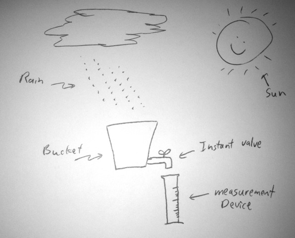
Imagine a bucket catching rain from the sky. It is open to the sky, and I have a valve on the bottom that will allow me to drain it into a graduated cylinder to measure how much is in the bucket. Now, imagine that I have the ability to instantly drain the bucket and read it out, and I do so every minute. So, once a minute, my mathematically precise instant valve opens and all the water drains out into my measurement cylinder. Now, it doesn’t stop raining while I measure, but that doesn’t matter because my measurement draining system is so quick.
If I do this, I have constructed an integrating sampling system. Over the entire minute of the integration, every raindrop is equally summed into my bucket. I am a happy rain-measuring guy.
So then, I want to know if I’m prefiltering before sampling. Well, certainly this system’s frequency response has been altered somehow. After all, if rain was a downpour for one second, then stops the next, then starts again, my bucket system wouldn’t really notice that, so somehow it has frequency response we need to analyze. So there is a frequency response to the system, which we can reasonably call a filter. It consists simply of the integration (my bucket). And the filter has a square-wave impulse response, or window. For infinite time before my particular sample minute, it’s got zero response to the rain (that was a different sample back then). Then it has 100% response to rain falling into my bucket for the minute of the particular sample. Then for all time forever in the future it has 0 response to rain (the bucket is being used for future samples then.) Let me draw this window:
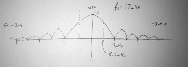
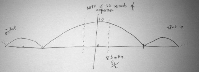
Notice that I’ve centered the integration window on the sample time, of zero. Physically, the entire integration happens and then our sampler will read out the bucket (which is the end of the integral). My readout into my measurement device drains the bucket completely. Because I am a fanatic about proper rain measurement, I then derive the frequency response. This is not hard, because this is a simple Fourier transform of this window. Because I’m interested in the power in the signal, I take the absolute value of the Fourier transform. With very little surprise, I see that it is this:
There are interesting things about this plot. First, it’s abs(sin(f)/f). In the frequency domain, it’s an infinite sinc function. It has nodes related to how long the original square wave was (60 seconds), which had a time of 60 seconds, so the first node is at 17mHz. 17mHz also happens to be our sampling frequency of the system.
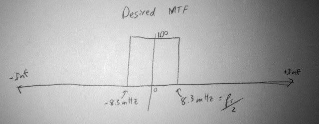
Now, because I adhere to good prefiltering before sampling, don’t care much for this frequency response. The Nyquist rate is 8.3 mHz, and by that point this MTF has dropped off a lot, and then this function continues to have lobes infinitely, which is no good. The prefilter response I want is:
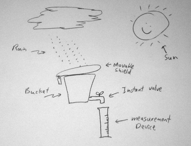
Ok, so to fiddle with the thing, decide the only thing I can really change here is my bucket’s response to incoming rain. I can add some device above the bucket that allows me to shape the bucket’s integration function. Since the shape of this integration function is the key determiner of the frequency response, that’s really the only thing I have to tweak this response. So I add a little movable shield on top of the bucket. With this, I can change how long the bucket is sensitive. Notice that my shield isn’t the sampling system. It’s just a shield. The sampling system is still the valve and the measurement device down below. My shield is part of the filter and integration. So I set up my shield so that it’s open for only 30 seconds, then closes for the other 30 seconds. My readout still happens at the same time every minute. (This is a 180-degree shutter).
My new frequency response is this:
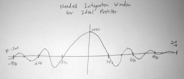
That’s not so great. I need something that falls off sooner, and this still has sidelobes that go on forever. So I reverse solve for what I need my integration function to be. That’s not hard, it’s the inverse Fourier transform from my ideal filter. Uh, oh, but there’s a problem:
This thing is a sinc function and is inifinite. I don’t have that much time for each sample (much less in my entire life). Remember, this is the function applied to the bucket for EACH MEASUREMENT I want to make. I really only have the bucket for 60 seconds for a sample. In other time periods, the bucket is occupied doing integration for other samples. So how can I implement this infinite window function (much less, how do I implement it going negative?) I can’t. It’s simply not possible with my bucket and the tools I’m limited with here.
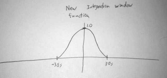
So I wonder to myself, can Tessive design me a better filter? It may not be the ideal I desire, but can it be better than this square wave thingy. The answer is: yes! If I can modulate the integration function, a whole world of new frequency responses opens up to me. They’re not perfect frequency responses, but they’re better than what I’ve got here. So I fiddle and tune, and come up with a new function. To do this, my sampling shield on top of the bucket needs to be made so that, at any particular instant in time, I can control what percentage of the rain falling makes it into the bucket. So I just open my shield partially. If I want 50% response at that moment, I open it so that it’s only covering 50% of the area of the mouth of the bucket. Here’s the new integration function I design to control the bucket-shield:
Notice that this is feasible. It’s not infinite nor is it negative. It happens during the 60 seconds I have for the integration before I make my measurement with my little valve.
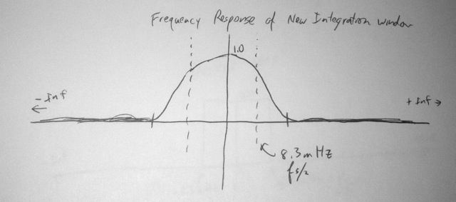
But what’s its MTF? Here it is:
So the MTF is much better than I had before. It drops off and pretty well stays dropped off by the sampling frequency. It’s got good response up to Nyquist, which is ok. I really wish it had less response between fs/2 and fs, but I’m feeling pretty good. I have a much better rain sampling filter.
This analogy is actually an extremely accurate representation of how a camera’s sensor works. Each pixel has an electron collecting well, and as photons rain in, they cause electrons to accumulate in this well. When readout occurs, that well is (pretty well instantly) transferred to the readout sample and hold amplifier. The transfer is very quick with respect to the framing times we’re dealing with, so it is effectively instantaneous. So we have a bucket integrating photons, and a separate readout device. All we need for better prefiltering before sampling is something to shape the integration.
Ok, that’s was a lot of typing, drawing, and iPhone picture taking. Did you follow it? Do you agree with what I’ve written so far? Don’t go too far yet; we have more questions to deal with. The question here is: can you make a filter with an integrator and by varying the integration window? The answer is unquestionably yes, but the point is to get agreement between you and I on this topic.
So what here seems wrong?
Tony
————————————————————————————————-
Here is John’s response:
Dear Tony,
I am not sure what you watched of mine, but I would clarify that what I said was not my merely my view. As an Expert Witness, the UK legal system requires me to abide by certain rules. One of these is that the opinions I give must not be pet theories of my own, but must reflect the consensus view of those skilled in the art. You can be assured that everything I have said so far and will say is stated on that basis.
It comes as a relief that you accept the fundamentals of sampling theory in your first set of points 1-4. My imagination is struggling with the concept of violent agreement. I’ve lived a sheltered life.
So let us move forward and consider your points one at a time, starting with your argument that your device implements a pre-filter of some kind.
The flaws in your argument are as follows:
a) Readout of the sensor does not serve the function of providing an infinitely short sampling instant. It simply moves the accumulated charge somewhere at a known time so it can be digitised. As the sensor is, we agree, a light integrator, the period over which light falls on it is the length of the sampling instant. Therefore the requirement for instantaneous sampling in agreed point 3 is not met and therefore there must be an aperture effect. We know that this is so because the in-band frequency response is not flat, because you sell a post equaliser and because your published MTFs show it. What you do not show is that a long integration time also damages dynamic resolution.
b) I was hoping to keep this debate on some sort of technical level rather than resorting to analogies, but here goes. The sensor is an integrator/bucket that counts photons/raindrops. Now, the sensor can be gated by the camera electronics and the light falling on the sensor can be gated by the Tessive device, which by your water analogy is some sort of programmable umbrella. So we have an AND gate for light. Both need to be gated on at the same time else no photons/rain can be integrated by the sensor/bucket. Now, if during the time the Tessive device is gated open, the sensor is gated on for a short period, the integration time, which is also the length of the sample instant, is determined by the sensor gate pulse. However, that is not how the Tessive device is used. It works the other way round. The camera is gated 100% open and the light comes in or not according to your LCD/umbrella. As a consequence, and this is pivotal, the length of the sampling instant, which is the integration time, and the sampling rate is determined by the Tessive device. According to sampling theory, the Tessive device is the sampler. It is a modulator and it creates sidebands which I could see by putting a photocell and a spectrum analyser behind it. No filter I am aware of creates sidebands. It follows immediately that if the sampling device is the first thing the light from the scene hits, then there is no pre-filter. By definition a pre-filter has that prefix because it goes before the sampling device. You do not have any form of filter before the sampling device. That is why your product cannot prevent aliasing between 12 and 40Hz. It is not until 40 Hz that the loss due to the aperture effect of your extremely non-zero sampling instant is useful. The aperture effect arises because of the non-zero time window of your modulator and the integration of the sensor. But the sensor is after your modulator. How can something that comes after be describes as a pre-anything?
So a rigorous analysis of a Tessive modulator in front of a 100% gated-on integrating sensor shows that there is no pre-filter. Instead there is an aperture effect. The presence of an extra pair of blades on a helicopter due to aliasing reinforces the analysis.
It seems to me that in the absence of a pre-filter, points 2 and 3 are difficult to discuss. However, you might usefully change point 3 to read “how is this aperture effect tested and demonstrated”, because I think we could find a good deal of agreement over what it does.
Best,
John
